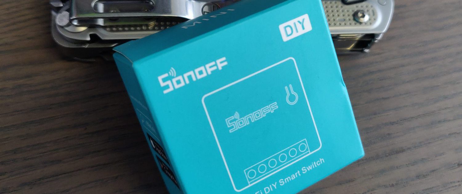
Supports Google Home, Alexa etc and costs less than €7 Euro.
So I’m sure I’m not alone in wishing I could turn on the heating on those cold and frosty mornings from the comfort of my duvet when the seasons change and your laziness hasn’t factored that in when it comes to setting up your existing thermostat.
You could of course install a Nest thermostat or have a Hive controller installed (Offered by gas suppliers here in Ireland. Not sure if its available elsewhere), but both of these options are pretty expensive for what is essentially a simple function. Flick the switch on the heating. 🙂
In it’s simplest form, we just want the ability to activate and deactivate the heating over the internet. Additionally, the ability to add schedules is a must when we’re talking about automating our home if we’re to make this more useful than sticking with the old dumb controller. Without schedules, we will have just moved a manual switch (or timer) to our smartphone. That’s still a manual switch even if I can control it from my sofa.
With this guide, you’ll be able to take your existing heating controller and replace it for a Sonoff Mini Smart Switch so that you can do all of the control from the palm of your hand, set schedules for ON and OFF timing, add scenes and integrate your heating with a smart speaker like Alexa or Google Home.
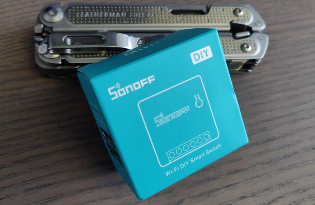
Sonoff Mini
So what exactly is the Sonoff Mini?
In simple terms, its a switch that can be flicked over the internet.
Right now, you can buy the Sonoff Mini on Amazon for €6.30 EUR / £5.65 GBP / $6.90 USD. You can connect this switch to any electrical devices in your home, from lights, heaters, plug sockets etc, so long as the devices don’t exceed the 10A rating of the switch and you can link them with Google Home for voice control or control them directly through a smartphone app.
The Sonoff has 6 terminals on the board for its inputs and outputs. These need to be wired into whatever device you intend to control in the home.
Mobile Application
For quick and easy setup, the Sonoff devices can be controlled with Sonoff’s own application from the Google PlayStore/app store. The app is called eWeLink and provides a nicely designed user interface for pairing and controlling as many Sonoff devices as you want. It also supports many other types of devices, but we’ll be looking specifically at the Sonoff Mini for the purposes of this guide. The app uses eWeLink’s own web services to control the Sonoff Mini over the internet when it receives commands from the mobile application, but one of the really neat features of the app is its ability to control the devices across LAN also. This is really helpful in the event that the device isn’t online or the internet is interrupted for whatever reason. It also improves the speed at which the Sonoff Mini responds to a command by directly receiving it from the app instead of doing so over the internet. Additionally, the app allows you to set schedules and states in an easy to use interface where you can also set up scenes for multiple devices. More on that later.
States
States is a pretty straightforward concept. It refers to the position the switch is in or the position you want the switch to be in at a given time. The switch can be in either of two states, ON or OFF. A manual press of the button in the app will toggle the state from whatever position it is in at that time to its oposite.
Schedules are slightly different to a manual toggle though. If the switch is already ON and a schedule tells it to turn ON again, the state will not change, but the time of activation will (this is important when we talk about inching later).
Where normal mode is used (without inching), a switch will stay on indefinitely unless the user set another schedule to turn it off, or they turned it off themselves manually. This is just something to keep in mind for when you’re deciding now long you would like your devices to be active after you turn them on. Maybe you don’t want them to stay on long after you’ve left the house etc.
In addition to states, there’s also a “Default State” setting in the application. This option allows you to set what you want the default state to be in the event of a reboot/power loss etc. In the case of your heating, you’re probably not going to want this set to ON, but in other situations such as maybe your security lighting, you might want that to always be active after a reboot.
Schedules
Schedules allow you to set exact times and days for a switch to be activated or deactivated by the eWeLink service. You simply pick the trigger times like you would if you were setting an alarm in your clock app and set the days you want it to happen on.
For instance, you can set a device to be active at 07:30am and choose whichever days of the week you want and this will become a recurring event on that time and day each week. You also choose the state to be “ON” or “OFF” for each trigger event. In the case of our heating system, lets say we want it to turn on at 7am and turn off at 8am. The first schedule is set at 7am and the state set to “ON”. The second schedule is set to 8am and the state set to “OFF”. So you get the point here, each state change is handled by another scheduled trigger. The schedules have no knowledge of each other and simply carry out their state command at the time chosen by the user. By default, we will have to tell it when to turn off the heating, or it’ll run indefinitely, so this is what the second schedule is for.
Also, Schedules don’t limit the ability to manually operate the switch. The user can turn on or off a switch whenever they choose, either using the mobile app or a normal switch that has been linked to the Sonoff Mini terminals 5 and 6.
Inching
So what then if for some reason the “OFF” state command isn’t received? Will my heating stay on indefinitely? That’ll cost a lot of money and my house will feel like the surface of Venus!
That’s where we come to another neat little feature of the eWeLink App. You can set the switch to “inching” mode. The name of this mode doesn’t do a great job of describing itself, but it is basically a toggle mode of “ON” then “OFF” (or visa versa) after a given duration. Imagine a scenario where you’re buzzing someone into a building. You don’t want to have the lock permanently disabled until you remember to re-lock it. Instead, you press a button and the lock disengages for a few seconds before locking itself again. Well that’s exactly what we have here with the inching mode.
When inching mode is activated, you’ll be asked to set the duration between the state changes. This is set to 0.5 seconds by default and can be set to a maximum of 3600 seconds (1 hour). In our case, we can set the inching mode to the maximum of 3600 seconds so that no mater what, once the heating is activated, it’ll turn off after 1 hour regardless and save us from running up a huge heating bill in the event that the schedule doesn’t turn it off, or we forget to do it manually.
If you want the heating to run for longer than an hour, you can just add another “ON” state in the schedule and the 1 hour inching countdown is reset. I don’t have much call for that duration of heating in my relatively mild climate so I’m happy with running it for an hour at a time, where needed.
Scenes
Scenes are my favourite feature of the application. A scene is a collection of smart switches that can all be controlled by the state change of a single switch in a kind of Master / Slave way.
For example, imagine I have a garden shed with some sockets, some lights inside and maybe a floodlight in the back garden to light my way, all connected with their own Sonoff Mini switches. If I want to head back inside the house, I might want to disable all of these circuits, so instead of opening up the app and toggling off 3 individual switches one by one, we can set up a scene which will toggle all three (or more.) when a given switch is toggled. Let’s say I set the scene on the floodlights switch. When that switch is toggled on or off, it can be used to toggle the state of all the other switches that are part of that scene. In addition to this, the slave devices don’t necessarily have to be switched to the same state as the Master. You can easily set up a scene that turns on motion sensitive floodlights when you shut down the shed power. You choose how each device in the scene reacts to the master device.
A scene can also have a lot of switches within it (I’m not sure if there’s an upper limit, but its a lot) so you aren’t limited to just 3 switches. You could have a scene that deactivates every switch in your house, if you wanted to go to the lengths of wiring enough Sonoff devices in.
eWeLink App Download
Click here to download the app
The Sonoff Mini Hardware – Explaining the Connections
In this section we’ll have a quick look at the hardware itself and explain the various terminals on the device.
It should go without saying, but any time you’re dealing mains power, you should disconnect the power to the circuit from the breaker/fuse box in your house.
Although this isn’t a very difficult installation, you should only attempt it if you are confident in your ability to complete the job and have at least some basic electrical experience.
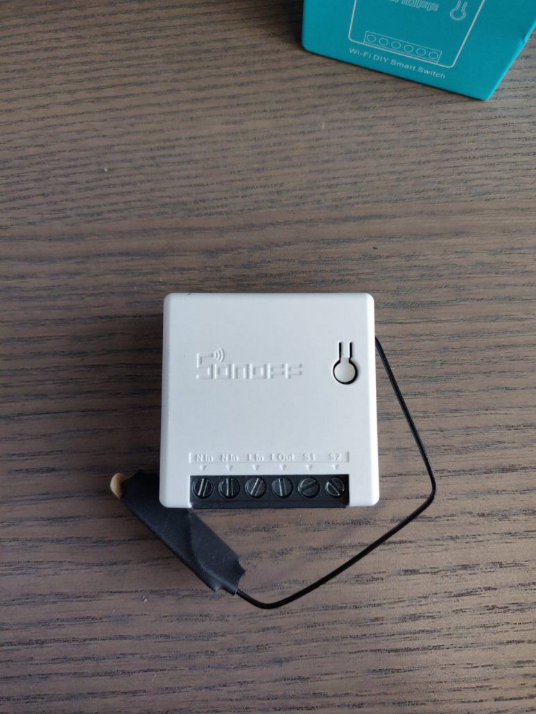
N – Neutral IN – Blue wire
N – Neutral IN 2 – Blue Wire
Permanent Live IN – Brown
Switched Live OUT – Brown Wire
Signal – Short to PIN 6 to trigger
Signal – Short to PIN 5 to trigger
Existing heating Controller – What to Expect
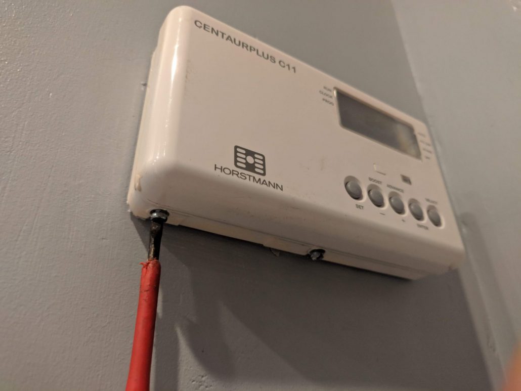
Your existing controller may vary from the one I have on my system, but generally they will all work in the same way and they share a standardised back-plate for the wiring connections. Mine is a CENTAURPLUS C11 by Horstmann. It is a basic heating controller that gives the user the ability to set up to 3 on/off cycles each day, with a “Boost” button to manually activate the heating for 1 hour where needed. Setting the timings on this controller is pretty tedious and we don’t have the ability to add more than 3 cycles, or have a specific weekend profile for the heating.
Out new smart heating controller will allow us to set many more than 3 cycles, and will even allow us to set specific profiles for different days of the week, so a big improvement on the old one. 🙂
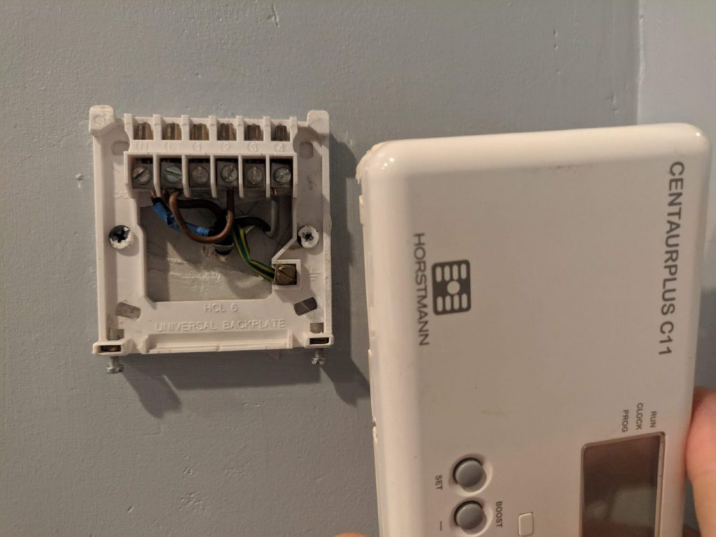
The C11 Controller has a number of wires coming through from behind the wall and the terminals are marked as described below.
- N – This is the neutral line and is connected back to the consumer unit/fuse panel uninterrupted. This is typically a blue cable in Ireland/UK, though a Black cable is used here because 3-core + earth wire was used. More often you’ll find 2-Core + earth will be used here instead. That’s not really important for now so I’ll try not to confuse things. You’ll see from the images that the wires in the N terminal are marked with a blue electrical tape. One of these wires goes to back to source at the consumer unit and the other is the Neutral power cable to the boiler.
- L – In the case of our C11 controller, the L line is the 220v Live line back to the circuit breaker in the consumer unit/fuse box. This is live at all times and is used to power the C11 controller, as well as powering the boiler. We’ll use this to power the Sonoff Mini when installing it.
- 1 – This terminal is not used in this configuration. Other configurations can be used where heating may have multiple zones (upstairs, downstairs etc) or the hot water circuit is separated from the heating. We don’t have to worry about this in my case. You can find more info about these features in the installation manual for your heating controller.
- 2 – The number 2 terminal has a jumper wire that goes back to the L terminal mentioned earlier. This means that the number 2 terminal is Live at all times also. Consider this terminal to be one side of the switch that will eventually activate the boiler.
- 3 – Just like the number 1 terminal, this terminal isn’t used in my configuration. This terminal would be the “Normally Closed” side of a switch and would be directly connected to the number 2 terminal by default, until the controller turns ON and breaks the connection between terminals 2 and 3.
- 4 – This terminal is the inverse of terminal 3. This one is “Normally Open“, meaning the circuit isn’t completed by default and will only be completed when the controller closes the connection. When this happens, terminal 4 becomes live. We can refer to this terminal as the “Switched Live”, as it’s only live when the heating is activated. You can see that there are some grey cables marked with brown electrical tape here. The Live feed on the boilers power cable goes to this terminal.
So we know that in order to power the Sonoff Mini, we need a Neutral line coming in, a Constant Live and a Switched Live. Simple, right?
Wiring in the new Sonoff to the old back-plate
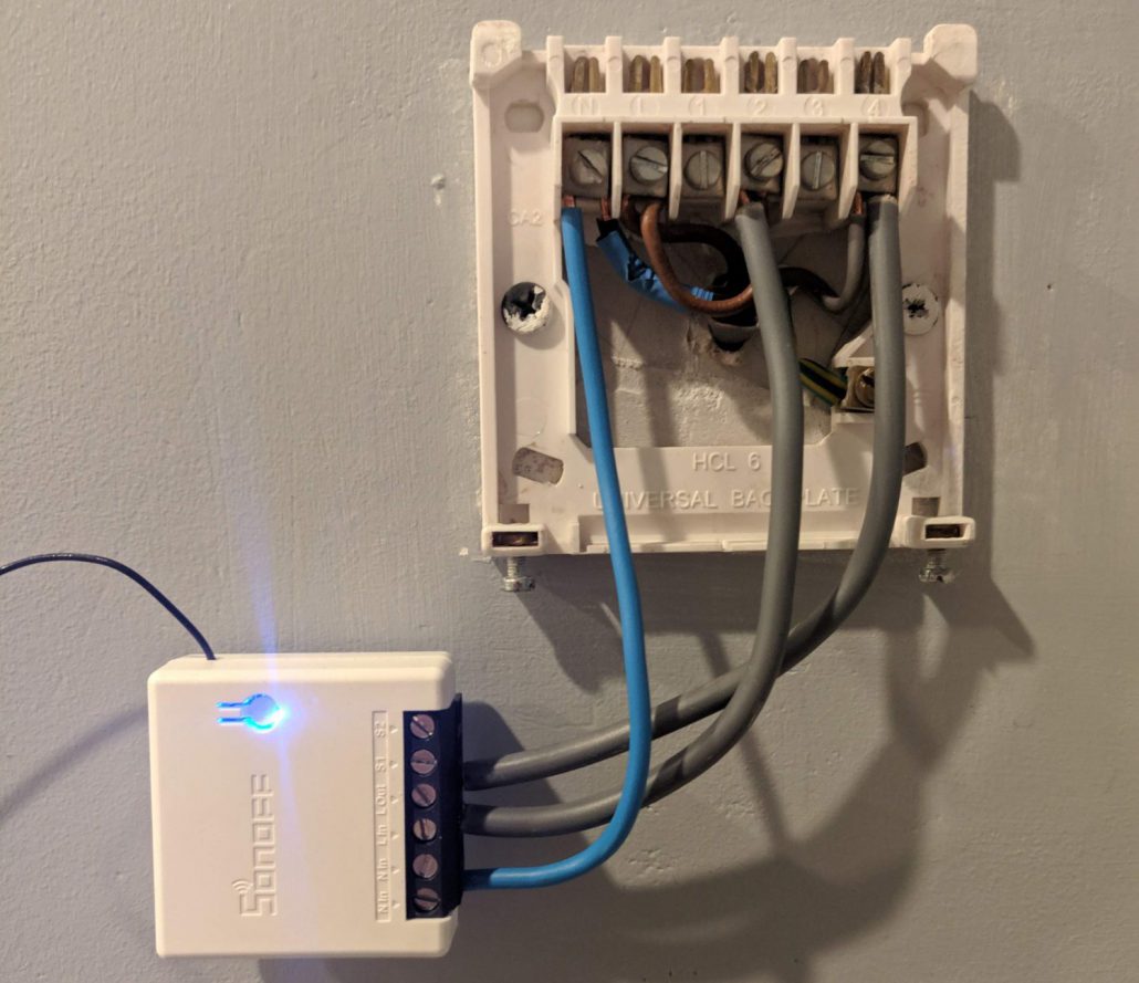
To try to make everything as clear as possible, I’ve added 3 pieces of wire to the Sonoff and attached them to the outside of this back-plate for the old controller. On my finished system, the Sonoff lives on the back side of this wall, but including that would add confusion to how it’s all wired up so I opted to just do a quick installation where the old controller used to live so you can see exactly whats going on. It’s not recommended to leave the Sonoff exposed, as the live terminals are easily accessible with your fingers so take this as a guide only. I installed mine on the back side of this wall inside a surface mounted box with a cover on top.
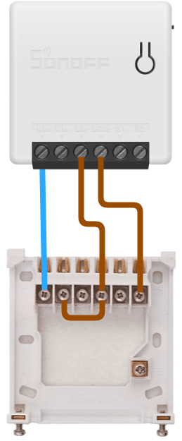
I added a Neutral blue wire to the Terminal 1 on the Sonoff. This is attached to Terminal 1 on the existing back-plate as shown in the photo.
On Terminal 3 of the Sonoff, I added a brown wire that is connected to Terminal 2 on the existing back-plate. This is the Constant Live side of the switch and also powers the Sonoff itself.
On Terminal 4 of the Sonoff I attached another brown wire and this is connected to Terminal 4 on the existing back-plate. This is the Switched Live side of the switch and goes to the boiler (or whatever you’re actually controlling with your setup). This is Live when the Sonoff state is switched to “ON” and in turn feeds power to the boiler.
Caution: I have used 2.5mm² wire, which is the standard used in my location and matches the cable of the existing heating controller. Be sure that any wire you use is up to standard and capable of handling the load of whatever it is that you are controlling. Depending on where you live, there may be regulations on what wire should be used.
Here’s a quick diagram I rustled up to better show where each wire goes.
Testing the Installation
Now that you have it all wired in correctly (and double checked…) You should be good to go for a test. Turn back on the electrical circuit from the consumer unit/fuse box etc and watch for the Sonoff coming to life. You should see the blue back-light coming to life behind the single button on the device. If all is ok, we can move on to pairing the device with the mobile app and see if everything works as it should.
Pairing the Sonoff to the App and Testing
At this point you should have a working WiFi switch with the blue light illuminated and ready to be controlled. To actuate the switch, you can either bridge the contacts on the Sonoff’s terminals 5 and 6 (Labelled S1 and S2. See Note below first) or operate it with the mobile application. Since we haven’t paired the mobile app yet, we’ll do that now.
- Open the eWeLink application and create an account/sign in.
- Select the “Add” button at the bottom and choose “Quick Pairing” mode.
- You’ll then be presented with a UI to set your WiFi details. Choose your network and enter the password and click Next.
- On the Sonoff Mini, press in the button for 5 seconds until the blue LED flashes rapidly. It’s now in pairing mode and is discoverable by the app.
- The mobile app will be searching for nearby devices and will show discovered devices on the screen.
- Once complete, you’ll be presented with a button interface where you can actuate the switch directly with the application.
The setup is now complete. You can repeat this for more Sonoff devices, or set some schedules and scenes if required.
Note: I don’t recommend bridging the terminals directly, as they are in very close proximity to some live cables that could give you a nasty shock if you aren’t careful.
You can add in some lengths of cable to pins 5 and 6 before reconnecting the power and use these to trigger the Sonoff. There’s no load across these 2 pins so there’s no danger there but be careful of pins 1, 3 and 4. If you have a manual switch you’d like to use, like a light switch or push button of some sort, you can wire it to the 2 cables at pins 5 and 6.
In my case, I ended up wiring things a little differently so that I could retain the old controller as well as the new WiFi switch, but that’s not really necessary for the purpose of explaining this installation.
See the images below for examples of the set up and pairing process.
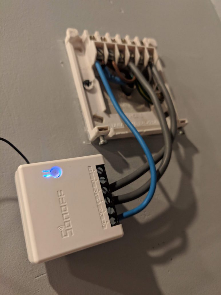
The blue LED is also the pairing button
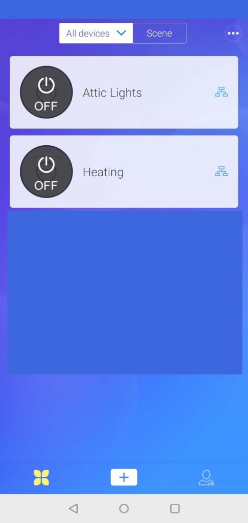
Click the “Add” button to add a new Sonoff Device.
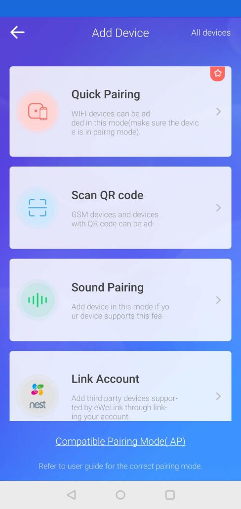
Choose “Quick Pair” from the options list.
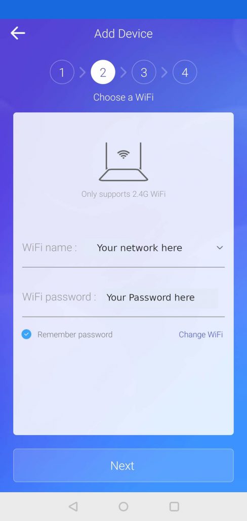
Enter your WiFi name and password.

Your device will now be paired and will show up in the list of buttons in the main UI.
Conclusion
So you should now have the device hardwired to the wiring from the old heating controller and paired with your eWeLink app. You can toggle the switch in the UI and see how it affects the WiFi switch and starts up the boiler.
If you’re happy that everything is working as expected, you can go about neatening up the cabling and adding an enclosure to prevent anyone from being shocked accidentally by touching the Sonoff Mini. It’s not recommended to leave it exposed.
I know there’s a lot of different kinds of boiler/heating system out there, so this guide should really only be treated as an indication of how your own DIY smart heating control might be achieved. I’ts recommended that you look closely at whatever system you currently have and see if it is comparable to my setup. I take no responsibility for any accidents or damage that might occur as a result of following this guide. Educate yourself and make sure you are reasonably confident before taking on electrical jobs of any sort.
Have fun. 🙂
What Next?
Now that you’re an IoT boss, you can take a look at some extra things you can do with a Sonoff Mini.
The device is built on an ESP based board and can be flashed with a custom firmware for additional features/customisation. One of the most popular is Tasmota. Tasmota provides a web UI for interacting with the device and a whole host of features for the home-gamer/developer to get stuck into. One of the big benefits of Tasmota is that it enables you to run the devices from your own server, so you aren’t dependent on any third party apps or web services. You could even develop your own phone apps or websites for controlling your home. You can find lots more info on Tasmota by clicking the link below.

