I’ve had my car for well over a decade now and still I find the odd upgrade I can add from time to time.
For a while though, I’ve been planning to add the turn signal indicator mirrors from the late model EP3’s. Well I finally got around to buying some from eBay, as I couldn’t stand looking at my lacquer pealing mirrors any longer. I couldn’t find a matching pair for a decent price online and finding some in my Vivid Blue Pearl colour was even more difficult so I just bought separate mirrors from a Milano Red and Nighthawk Black Civic. Since I wanted to do some touch-ups elsewhere on the car anyway, I didn’t mind having to paint them.
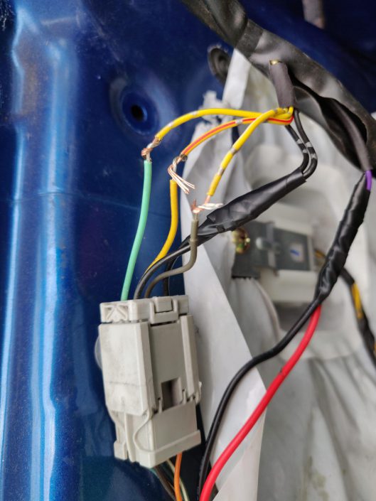
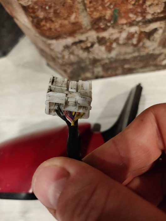
The real challenge with these type of mirrors though, is the wiring. Honda used an entirely different wiring plug with these mirrors when compared with my original mirrors, as there is an additional 2 wires for the indicator itself. This means I have to add in some wiring from the side repeater and through the door grommet, up to the connector for the mirror under the door card. Unfortunately, the wiring colours they used are also completely different from the basic setup too.
So I set about figuring out a wiring diagram. First stop was to check online and see if anyone else had already done the leg-work, but I found some contradictory information. I was going to have to just get stuck in.
First things first, crack open the entire mirror for a closer look. Since I’ll be painting them, I needed to strip them down anyway. I was able to identify the 2 wires that go to the indicator and another 2 that go to the heater element. This left only 3 wires to figure out.
To complicate matters slightly, the wiring colours are different from the left mirror to the right one.
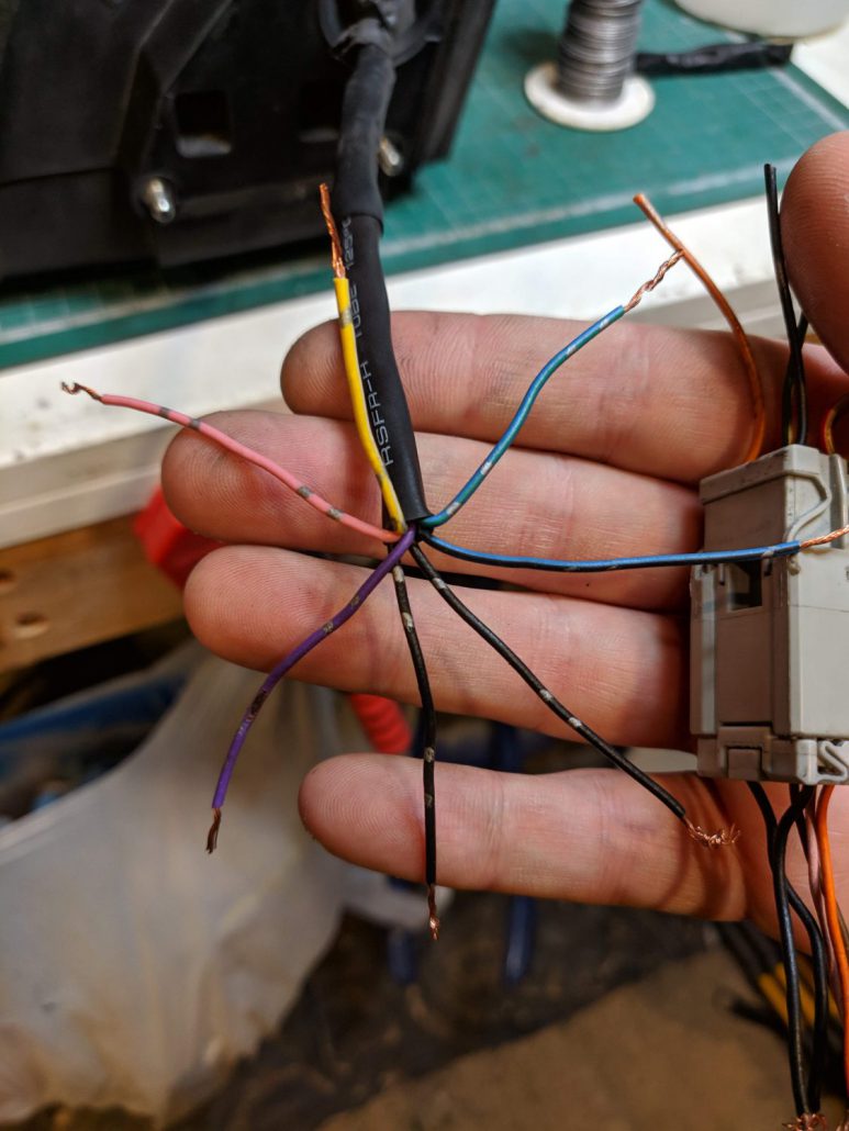
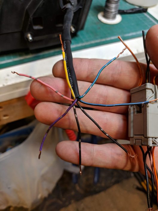
Working from the right (drivers side) mirror, I identified that the Pink and Purple wires were the 12v and Ground of the indicator LED in the mirror. In addition, the 2 Black wires were for the mirror heater. It doesn’t matter which way around these actually go when attached to the mirror. This left us with a Yellow, a Blue/Black and a Blue/Green on the drivers side, and Light-Green, Yellow and Grey on the left/passenger side.
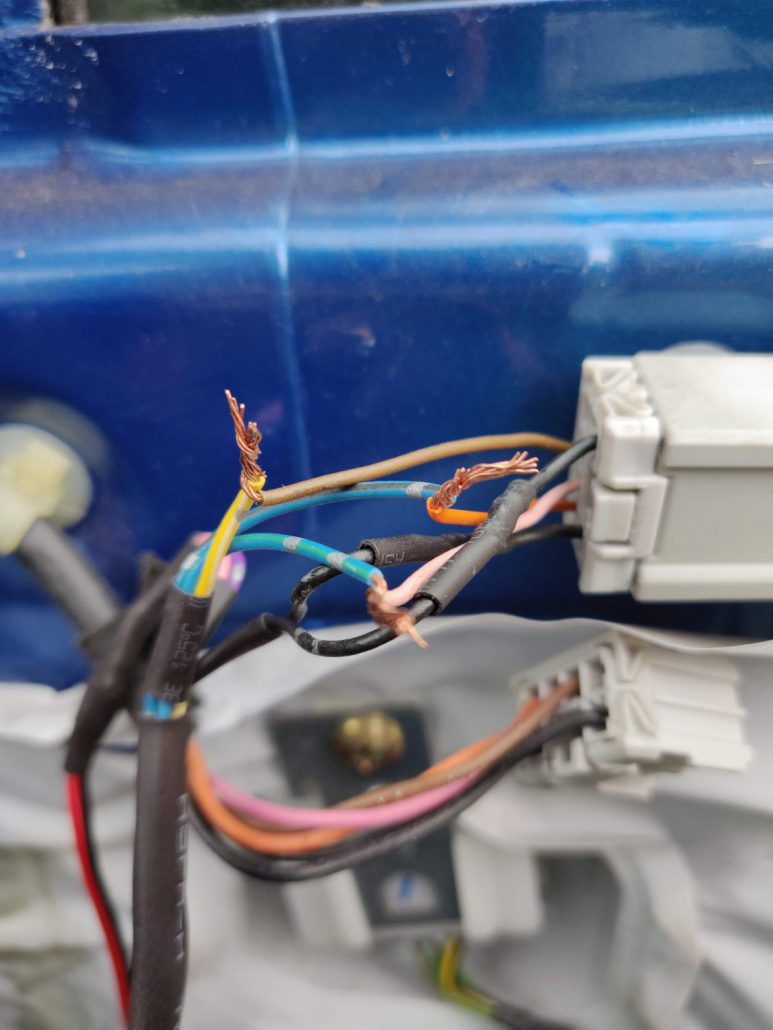
You can see I have paired up some of the wires in the next image. This is the drivers side (right side) turn signal mirror.
Different Wiring Connectors
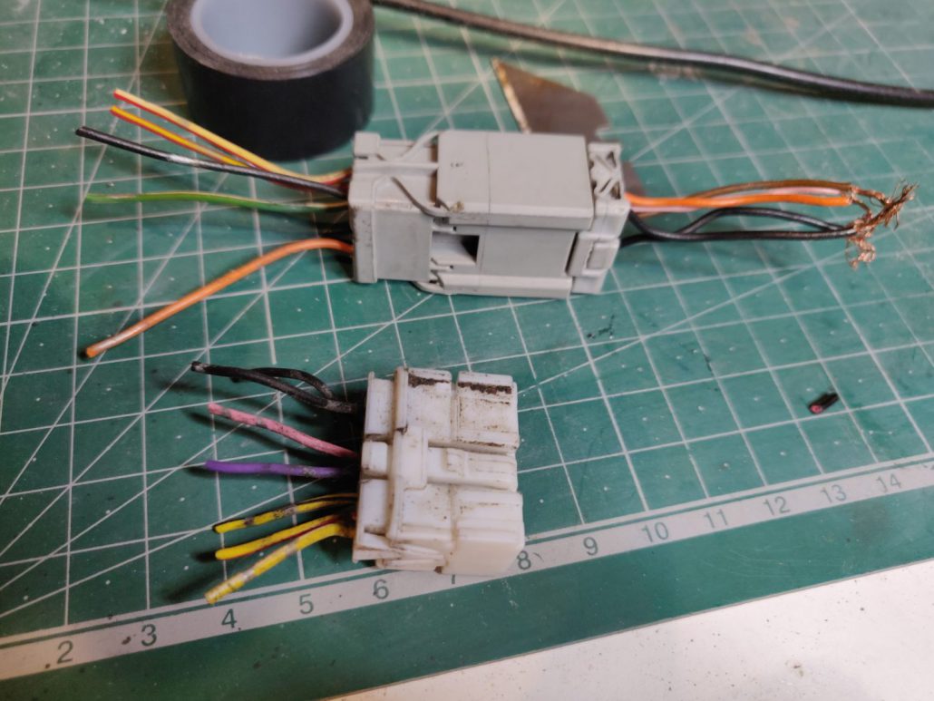
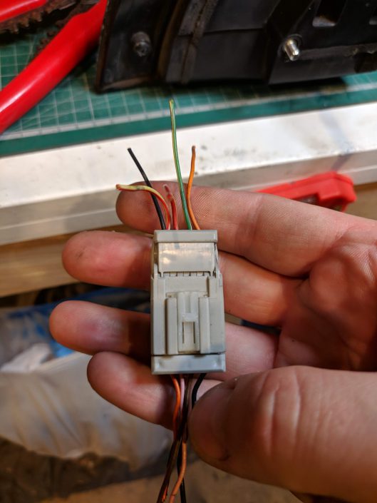
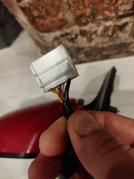
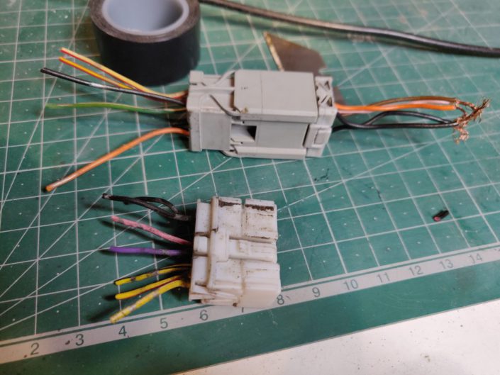
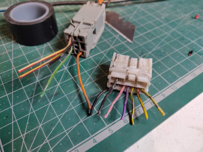
In the next image you can clearly see the difference between the older and the newer style of electrical plug that Honda have used. The on at the top is the older 5-Wire type and the newer 7-Wire type is below in the pic.
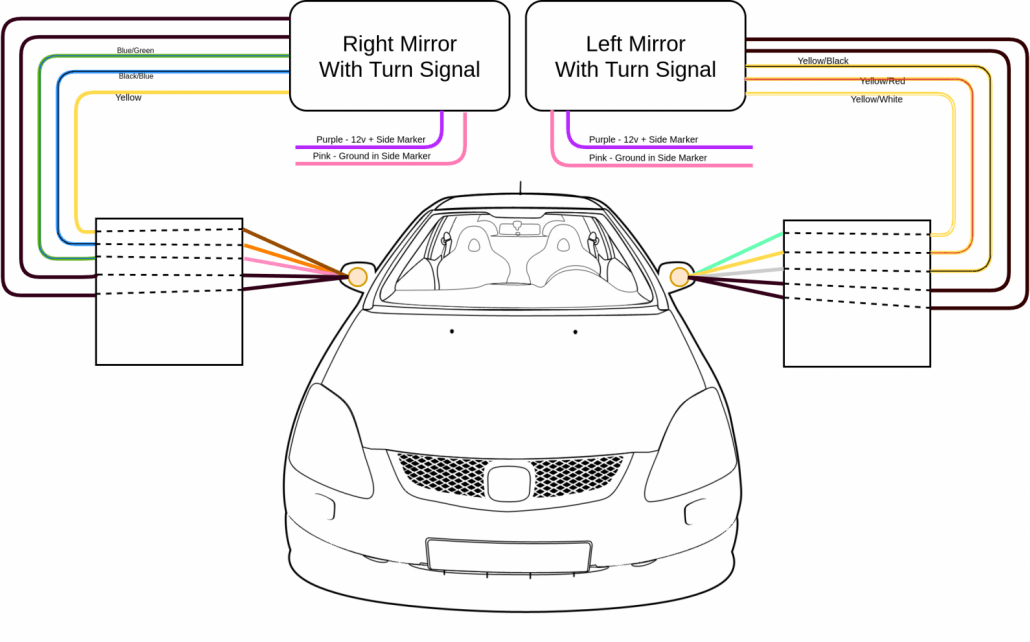
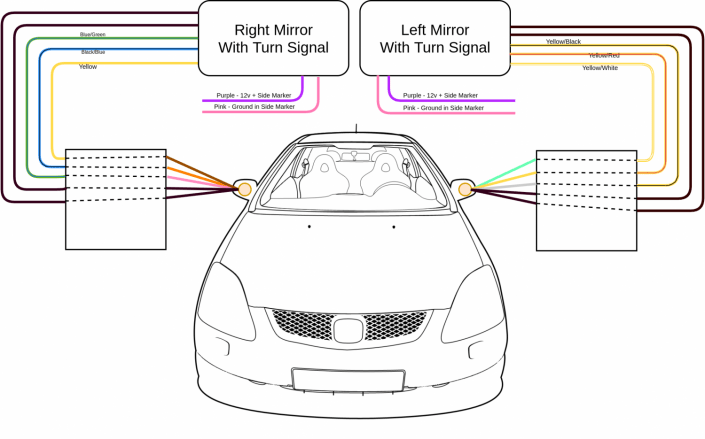
In both cases, the heated mirror wires are the 2 black wires so that helps us narrow it down a little. After that though, there’s no relation between the wiring colours so we have some investigating to do. They also differ from left side to right, but I have made a wiring diagram to make sense of this.
My Wiring Diagram
I spent a while writing out details of which wire is which for each mirror, since the colours are different from side to side, then I figured, Hey, why not just draw a diagram and save all this reading? So that’s what I did. The graphic of the car I used was by a user on devianart by the name of Castroreale. You can check them out here:
Click on the image to view full size.
Basic Mock-Up Test
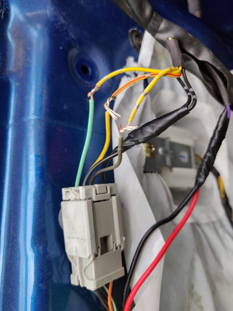
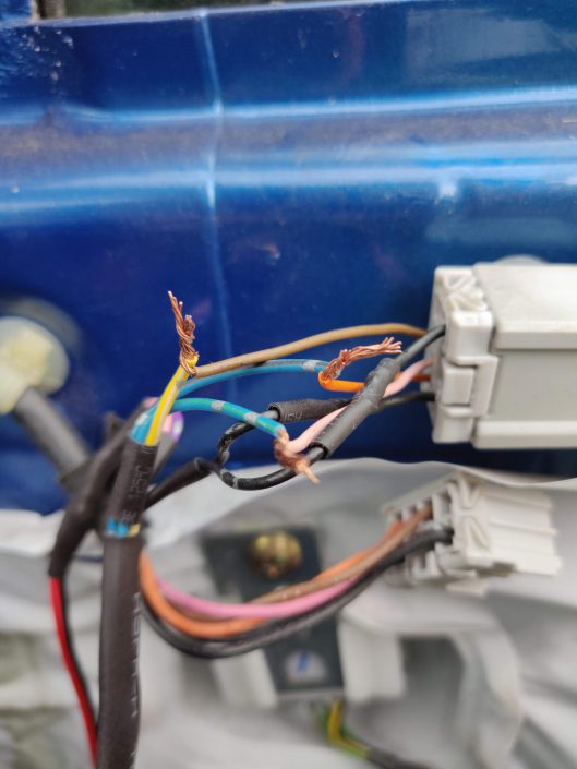
So once I had a good idea of how exactly the wiring was going to work out, I loosely fitted the mirror and just did some twist joins on each cable. I knew the black wires didn’t really matter in terms of which way around they go, but if you mix up the other 3 then you can have issues with the mirror moving the wrong direction, or moving in two directions when you are positioning it with the control switch in the car. Once I was happy with how it all worked, I cracked out the soldering iron and heat shrink to give it a solid connection. I wouldn’t recommend twisting the wires as a permanent solution.
Left/Passenger side Mirror (click for full size)
Right/Drivers side Mirror (click for full size)
Figuring out the Indicator Wiring
All of the wiring for the movement is pretty straightforward once you get your head around it. This left me only the indicator wiring to figure out. Since this car didn’t have turn signals in the mirrors, there isn’t any harness to plug them in directly so I had to run some wire from the side repeaters in through the rubber grommet in the door and up to the plug for the electric mirror. Initially I thought I would have to run it from the side repeater itself but on closer inspection, I saw that the side repeater come in through the bulkhead and plugged in very close to the harness that goes through the door. This meant I didn’t have to run a lot of cable or make complicated routes though the wing.
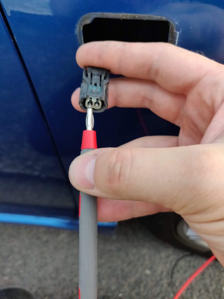
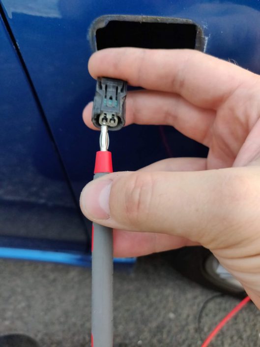
I didn’t take a photo of that part unfortunately, but if memory serves me correctly, the 12v + for the side repeaters was a green wire. You can see me testing the side repeater plug here to identify which was the live side.
The left side of the plug is the 12v +.
Customising the Indicator
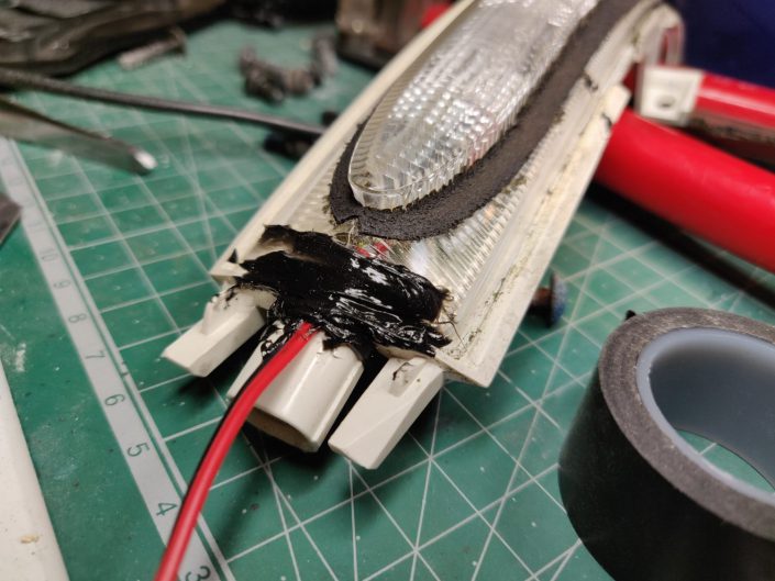
All sealed up and ready for reassembly.
Up until this point everything has been pretty standard. I could just tap the indicator wiring into my original side repeaters and leave it at that. Instead though, I found these LED “running” kinda strip light that mimics the turn signals often seen on some fancy modern German cars so my mission was to upgrade the basic LED that was contained within the wing mirrors.
That was no easy feat though. The LED unit is completely sealed and next to impossible to split open without ruining it. I had a quick look online to see how easily I could get a replacement LED before going at it with levers etc and since they weren’t all that easily available, I opted not to try and open it.
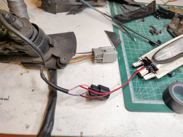
Instead though, I hatched a plan to dremel away a small channel at the end of the LED where its internal plug attaches so that I could slip the new LED strip down into the housing. There was just enough room to wiggle the strip in and after a few tries, it was right were I wanted it. I then sealed up the little slot I had dremeled with some high temp silicone I had knocking around. This would insure I didn’t get any water getting inside the LED housing and cause it to get foggy in the future.
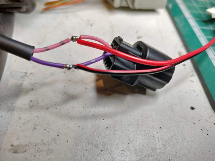
You can see in the image that I soldered the wires to the existing harness inside the mirror. I then left this unplugged and tied with a cable tie so that it didn’t move around.
The Resulting Effect
I did a little test on my work bench to show the effect of the running LED vs the basic LED that comes as standard in the mirror. It’s a subtle upgrade but I when it’s all back together it looks great. It’s often the mods that don’t stand out as aftermarket that I find most rewarding.
Old Mirror vs New Mirror
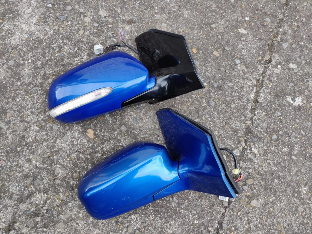
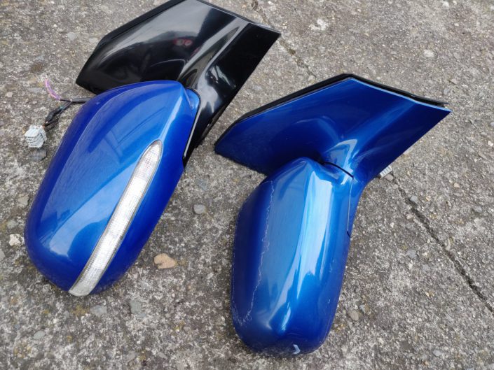
At first glance, they don’t really look that different when on the car, but when you have them side by side you can see they’re completely different mirrors. The turn signal mirror is wider than the original and has more of a bezel around the glass. I’m not sure if they have interchangeable glass though.
My original mirrors where showing there age with a lot of lacquer peal so having these nice newly painted mirrors on the car makes a big difference. Originally, my mirrors had unpainted black bases by I colour-coded them about 15 years ago so I’m pretty happy to see that my paint job out lasted the lacquer on the factory mirror. 😀 Since I was painting the new mirrors though, I decided to go with gloss black bases to give a nice bit of contrast against the metalic blue paint. I really like how it turned out.
Wrap Up
So that’s pretty much it for the little project. I know others have done this mirror upgrade too, but I haven’t seen it done with the running indicator in there so maybe it’ll prove useful for anyone considering doing the same. I have added a gallery of random photos of the project below that might be helpful.

